ATTINY85 NeoPixel bicycle led light

I wanted better side visibility when riding my bike back from work at night.

I used two long servo cables to connect the  ATTIny85 board to the Neopixel LED strips, and some hot glue to hold things in place

Mounted it to my rear rack with a USB battery pack.

0120faf2d010af3f65588e42edf566a8b9978dc0a4

Added ATTiny ISP circuit on board for easy reprogramming using Evil Mad Science Labs Arduino ISP shield.

attiny_combined

Matias Mini Quiet Pro FK 303 keyboard scan matrix

I have been using a Matias Mini quiet Pro keyboard at work for a while now. I recently decided to replace it with a KB Paradise V80 (also with Matias quiet switches) to match the TKL layout of the keyboard I use at home. This was mainly because the different key placement between my home and office keyboard was driving me crazy. Using the standard TKL layout is nice, but the thing I miss the most about the mini quiet pro is the stealth space bar, which has to be the least noisy spacebar I have ever used. I should post a comparison video/audio of it someday.

matias1


By inspecting the photos posted on a review of this keyboard I realized that the keyboard controller daughter board was replaceable. So I decided to make a Teensy based replacement controller board so that I can make custom key mappings to fix some of my issues with this keyboard:

  • Change page-up, page-down to home and end
  • Change F12 to default to insert, and Fn+F12 to F12
  • Change caps-lock to Fn

01d0cc6720540417bb95fa4e78492d0c3b26f642a8

Opening the keyboard involved removing two screws on the back (thankfully without any warranty void stickers) followed by using plastic cards to push in the 7 tabs holding the top plate to the bottom plate. The plastic tabs are fairly sturdy but I somehow managed to break one of them the second time I opened the case, so do be careful about not pulling apart the top half till all the tabs are released.

DSCF5539

The key switches are mounted on a metal plate and soldered on to the two layer FR4 PCB. The daughter board with the 1×4 USB hub chip (Genesys logic GL852G) and keyboard controller (Weltrend WT6522, uses one of the 4 hub ports) mount on a daughter board which connects to the main board via 2mm header pins. The keyboard scan matrix is wired up to the two 17 pins sockets, which for some reason are offset by 1.5 pin width (1.5 * 2mm = 3mm). The other two sockets are used for the three USB hub ports.

DSCF5528DSCF5537

DSCF5533

After some googling I came across this post about reverse engineering the keyboard scan matrix. I mostly followed the directions from that post but with the following important additions:

  • Since one of the keyswitch terminals is connected to the scan row/column via a diode the polarity of the multimeter probes matters. I placed the black/common probe on the keyswitch terminals and scanned the pin headers with the red probe.
  • The left terminal seems to have a diode on most keys – and I named it pin 2, and the right terminals as pin 1 for each switch.
  • The pin with the diode made a blip sound vs. continuous beep sound for the pin without the diode.
  • As you scan though the keys remember to make note of which key blips vs. beeps
  • Build a table and use rows for pins that go blip and columns for pins that go beep, and add the PCB screen print label at the intersection of the row and column


0144a5aaffcf6cf087d1204cac77a4fa6305c60d9a

Scanning through all the keys took somewhere between 2 to 3 hours with multiple breaks taken in between. And then another hour to analyze and compile the data and find measurement bugs/typos.

Google drive spreadsheet with scan matrix details here.

Next I need to figure out how to make a PCB for this in Eagle/KiCAD and then map the pins to a Teensy 2.0++ board.

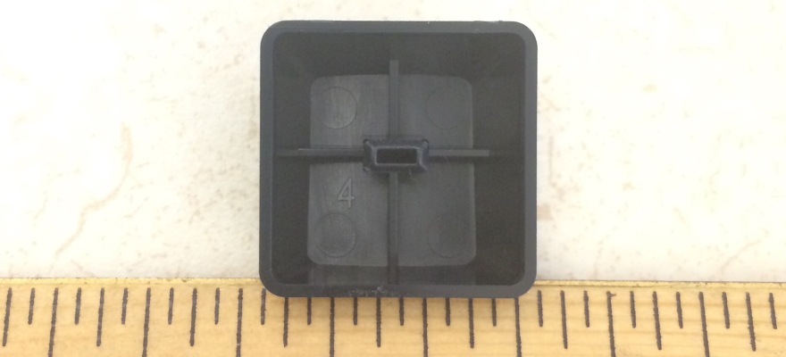
Keycap comparison

Cooler master Quick Fire ABS vs. KB Paradise V80 double shot ABS vs. Matias Mini Quiet pro ABS:


Cat feeder servo Motor upgrade

This weekend I upgraded our Cat feeder from the Parallax continuous rotation servo motor to the more powerful and faster PowerHD continuous rotation servo from Pololu bought during their black friday sale.

Also used the opportunity to wash and clean up the Zevro KCH-06138 dry-food dispenser.

The servo coupler, mount, hubs, gears, plastic link chain, misc. hardware was sourced from ServoCity and my local hardware store.

The arduino Diavolino and chronodot came from EMSL, the bluefruit from adafruit, and other stuff from seeedstudio, mouser etc.

Thing still left to try out:

  1. Reduce the serving size
  2. Better SW debouncing the rotary encoder
  3. Test and check with larger quantities of food

Frosty Flake controller for Cooler Master Storm QuickFire Rapid keyboard

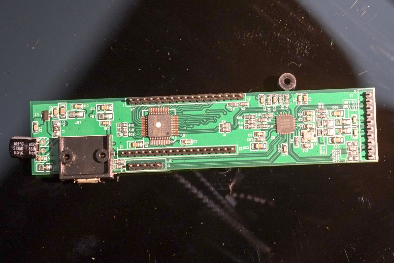
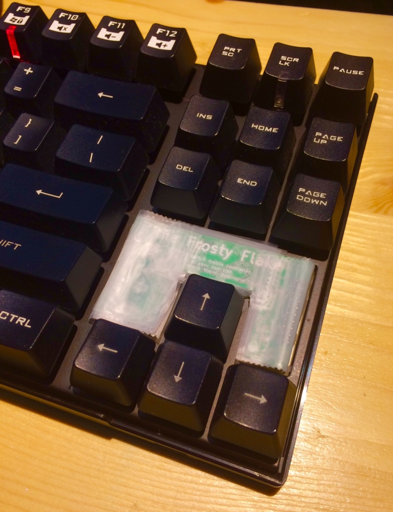
After a sudden brain wave last week I had been googling to see if anyone of the mechanical keyboard models had easily modifiable firmware and realized that the very keyboard I was typing on had a removable daughter board… and there was already a ATmega32U2 (note U2 & not U4) replacement controller available for it called the Frosty Flake.

I ordered one of these and will be documenting my changes to the firmware here. Here are a few photos of it next to the original board (thinner and flimsier).

I also decided to remove the top plastic cover on my keyboard to give it a more naked look and taped up the controller to avoid shorting it. I plan to make a transparent acrylic laser cut cover for the Frosty Flake.

01d135d9843b976dcbb92e615f0c9c0427f32cd37b

Power Raspberry Pi directly with Lithium Ion rechargeable batteries

From reading Adafruit’s excellent dissection of the (then new) RPi Model B+ power supply I had learnt (from the schematics) that 5V GPIO pin was directly connected to RT8020AGQW step down DC/DC converter (5v to 3.3V/1.8V) which automatically switches to a low-dropout mode.  So it should be possible to power a RPi B+ with much less than 5V at the GPIO 5v pin. Relevant excerpts from the data sheet:

Two operational modes are available : PWM/Low-Dropout auto-switch and shutdown modes. Internal synchronous rectifier with low RDS(ON) dramatically reduces conduction loss at PWM mode. No external Schottky diode is required in practical application. The RT8020 enters Low-Dropout mode when normal PWM cannot provide regulated output voltage by continuously turning on the upper PMOS.

Rds_RPi

Since I did not have the right equipment to test for this at that time I tried calculating it from the datasheet. Assuming a worst case Rds of 0.5 ohms for the PMOS at a current of 700mA (model B+, camera module, USB wireless) I get a voltage drop of 0.35V across the PMOS. So if we ideally want 3.3v at the output, then VIN should be 3.65V. At this point I should add that I am not completely sure if that is the correct way to estimate the dropout.

Now that I own an adjustable power supply I wanted to test that out. The only RPi I had on hand was a model A+ so thats what I used.

DISCLAIMER: All numbers below are from a very rough test and come with no guarantees. This means that if your house burns down or something terrible happens because of using something I said then I am not  to blame for that.

Test A:

I tried booted the RPi at 5V, with a keyboard and HDMI monitor connected. Then I launched Minecraft (wish the RPi foundation included a stability testing benchmark) and started lowering the voltage. For the short duration of time that I tested I was able to run without any brownouts at 3.5V. Going lower to 3.4v or even 3.45V would cause random reboots, which brings us to the next test.

01945a9c7fc4c34230ff0884c13f99afb23d015780

Test B:

While the RPi was rebooting I increased voltage back to 3.5V but noticed that was not sufficient and the RPi stayed stuck in a continuous reboot cycle. I was able to see the RPi booting up messages but at some point during that it was get reset. In hindsight I should have tried to make a video to figure out when exactly the reset happened. I next tried 3.6V which also did not work. I was only able to stop the reboot cycle at 3.7V.

01a07dcba2cc9da5ee10bc21b2964d116874a85c34

Test C:

Next I unplugged the keyboard and plugged in wireless dongle and again tried lowering the voltage. I was able to sustain a download over wifi with X server loaded at 3.5V.

Conclusion

The calculation was fairly accurate and as expected the model A+ was able to operate at a lower voltage than calculated because of using less current.

Coming back to the title of this post, I went down this path because I wanted to minimize components and was wondering if I could directly power the RPi for my remotely controlled home rover from the Li Ion battery. Searching for lithium ion battery discharge curves I see that at 1C rate reaching 3.5V would be somewhere in the 60% to 80% discharge capacity of the battery. So if I want to use the full battery capacity I should use a step-up converter, but if I don’t care about that I should be able to power up a Rpi with a lithium battery connected directory to Vin. Monitoring the current and voltage to the RPi might also be a good option to ensure stability to raise early warning if the voltage goes too low.

Relevant products:

Adafruit INA219 breakout to monitor current and voltage to the RaspberryPi.

CPS-3205 power supply bought from ebay

Lenovo ThinkServer TS140

-under construction-

I recently got an Intel Core i3-4130 variant of the TS140 for a great price ($230) and have set it up as my home Linux file server, which I intend to put to use to replace a Synology NAS that I am using currently.

This place holder post will get more details of the setup over the next few weeks.

Things I am planning to try:

1) Kubuntu

2) btrfs/ZFS mirror

3) timemachine

4) samba

5) UPS nut client server

6) Airprint

Serial interface for EiBotBoard (EBB)

I received the WaterColorBot last December (that I had ordered from EMSL through Kickstarter) and have been having fun using it in RoboPaint.

As I read more about the EBB board being used to drive the two stepper motors and the servo I was surprised to find out that serial over USB seemed to currently be the only way to connect to the PIC18 board.  So I decided to see if I could supplement the serial USB with a direct 3.3v UART interface. This would allow direct control of the EBB projects from other micro-controllers without having to store the motions in the EBB firmware.

ebb

I am currently reading through the firmware I downloaded from the EggBot google code repository, and have also been able to download the toolchain and flash the board with a modified firmware following instructions from here. This is also my first foray into PIC18 programming. I will update next when I some something more substantial than just an intention (unlike this time).

One of the first things I did here was to figure out how to connect to the EBB board over usb emulated serial. I had to read through the source code for robotpaint-rt to figure out the baud rate.

~ > miniterm.py -p /dev/ttyS2 -b 38400
--- Miniterm on /dev/ttyS2: 38400,8,N,1 ---
--- Quit: Ctrl+] | Menu: Ctrl+T | Help: Ctrl+T followed by Ctrl+H ---
--- local echo active ---
v
EBBv13_and_above EB Firmware Meow Version 2.2.3

Note that the version string above says “Meow” because I updated the firmware on the EBB board when I was testing the instruction I got from Brian Schmalz.

Link to EBB command reference, but it somehow does not mention the “V” version command.

I have figured out how to configure a second serial port on the board (see photos below) but have not updated the firmware to use it for commands yet.

01a6bbc1e7fe5dd913f6aca458f4e0406ae7338ea7

Open Case for Jetson TK1 board

I was feeling a little uneasy about not having a case for the NVIDIA Jetson TK1 board as I was very frequently connecting and disconnecting to it.

So I decided to buy a few 4-40 standoffs and screws from Anchor Electronics and quickly put together an open case for the board using some scrap wood I had lying around.

The whole in the top plate in the following photo was from when I had used a hole saw on that scrap piece.

Jetson TK1 case

Considering how loud that fan is I would not be surprised if I end up putting the board in a box. I am anyway keeping it inside the closet to keep it as far away from my desk at home as possible.

What were they thinking putting such a loud fan on a board this small.

Flashing the rootfs on a NVIDIA Jetson TK1

I some how managed to mess up the file system on my Jetson TK1 within 2 days of receiving it and decided to start afresh by flashing back to the original rootfs.

NVIDIA provides a quick start guide on how to do this here on its Linux for Tegra R19 webpage. I am essentially paraphrasing those instructions so that I can get this done quicker the next time. Since the instructions are specific to release version it is possible that they could change for the next release.

13910367357_ab79328a39_b

You will need:

  1. A Linux host PC with enough free space on which you will prepare the file system before flashing it to the eMMC on the TK1 board over USB.
  2. micro USB to USB cable (should be included with the Jetson TK1 kit)

Download the following two files into the same folder:

  1. Jetson TK1 board support package aka BSP (called Tegra124_Linux_R19.2.0_armhf.tbz2) from here.
  2. Sample file system file (called Tegra_Linux_Sample-Root-Filesystem_R19.2.0_armhf.tbz2) from here.
mkdir tk1_reflash
cd tk1_reflash
wget https://developer.nvidia.com/sites/default/files/akamai/mobile/files/L4T/Tegra124_Linux_R19.2.0_armhf.tbz2
wget https://developer.nvidia.com/sites/default/files/akamai/mobile/files/L4T/Tegra_Linux_Sample-Root-Filesystem_R19.2.0_armhf.tbz2

Extract the BSP tarball:

sudo tar xpf Tegra124_Linux_R19.2.0_armhf.tbz2

Extract the FS tarball into a particular sub directory:

cd Linux_for_Tegra/rootfs
sudo tar xpf ../../Tegra_Linux_Sample-Root-Filesystem_R19.2.0_armhf.tbz2

Apply binaries:

cd ..
sudo ./apply_binaries.sh

The following output will be seen:

Using rootfs directory of: /home/you/tk1_reflash/Linux_for_Tegra/rootfs
Extracting the NVIDIA user space components to /home/you/tk1_reflash/Linux_for_Tegra/rootfs
Extracting the NVIDIA gst test applications to /home/you/tk1_reflash/Linux_for_Tegra/rootfs
Extracting the configuration files for the supplied root filesystem to /home/you/tk1_reflash/Linux_for_Tegra/rootfs
Creating a symbolic link nvgstplayer pointing to nvgstplayer-0.10
Adding symlink libcuda.so --> libcuda.so.1.1
Extracting the firmwares and kernel modules to /home/you/tk1_reflash/Linux_for_Tegra/rootfs
Installing the board *.dtb files into /home/you/tk1_reflash/Linux_for_Tegra/rootfs/boot
Success!

Write to eMMC over usb:

  1. Put your system into “reset recovery mode” by holding down the “RECOVERY” button and press “RESET” button once on the main board.
  2. Ensure your Linux host system is connected to the target device through the USB cable for flashing.

Verify that board was connected by running:

lsusb | grep -i nvidia

You should see the following:

Bus 002 Device 004: ID 0955:7140 NVidia Corp.

Next run the following command. I think the eMMC is supposed to the 16GiB, but I just used the exact command from the NVIDIA readme assuming that I should be able to resize it later.

sudo ./flash.sh -S 8GiB jetson-tk1 mmcblk0p1

UPDATE: The above command will leave space unused as pointed in the comments. To use all of the eMMC use “-S 14580MiB” (from: http://elinux.org/Jetson_TK1#If_you_need_more_disk_space_on_the_eMMC)

This should print something like the following and will take a loooong time:

copying dtbfile(/home/foobar/l4t/Linux_for_Tegra/kernel/dtb/tegra124-pm375.dtb) to tegra124-pm375.dtb... done.
Making system.img... 
 populating rootfs from /home/foobar/l4t/Linux_for_Tegra/rootfs... done.
 Sync'ing... done.
System.img built successfully. 
copying bctfile(/home/foobar/l4t/Linux_for_Tegra/bootloader/ardbeg/BCT/PM375_Hynix_2GB_H5TC4G63AFR_RDA_924MHz.cfg) to bct.cfg... done.
copying cfgfile(/home/foobar/l4t/Linux_for_Tegra/bootloader/ardbeg/cfg/gnu_linux_fastboot_emmc_full.cfg) to flash.cfg... done.
creating gpt(ppt.img)... 
*** GPT Parameters ***
device size -------------- 15766388736
bootpart size ------------ 8388608
userpart size ------------ 15758000128
Erase Block Size --------- 2097152
sector size -------------- 4096
Partition Config file ---- flash.cfg
Visible partition flag --- GP1
Primary GPT output ------- PPT->ppt.img
Secondary GPT output ----- GPT->gpt.img
Target device name ------- none
*** PARTITION LAYOUT(16 partitions) ***
[ BCT] BH 0 16383 8.0MiB 
[ PPT] UH 0 4095 2.0MiB ppt.img
[ PT] UH 4096 8191 2.0MiB 
[ EBT] UH 8192 16383 4.0MiB fastboot.bin
[ LNX] UH 16384 32767 8.0MiB boot.img
[ SOS] UH 32768 45055 6.0MiB 
[ GP1] UH 45056 49151 2.0MiB 
[ APP] UV 49152 16826367 8192.0MiB system.img
[ DTB] UV 16826368 16834559 4.0MiB tegra124-pm375.dtb
[ EFI] UV 16834560 16965631 64.0MiB 
[ USP] UV 16965632 16973823 4.0MiB 
[ TP1] UV 16973824 16982015 4.0MiB 
[ TP2] UV 16982016 16990207 4.0MiB 
[ TP3] UV 16990208 16998399 4.0MiB 
[ UDA] UV 16998400 30773247 6726.0MiB 
[ GPT] UH 30773248 30777343 2.0MiB gpt.img
done.
copying bootloader(/home/foobar/l4t/Linux_for_Tegra/bootloader/ardbeg/fastboot.bin)... done.
Bootloader(/home/foobar/l4t/Linux_for_Tegra/bootloader/ardbeg/fastboot.bin) used as flasher.
Existing flash application(/home/foobar/l4t/Linux_for_Tegra/bootloader/nvflash) reused.
making zero initrd... 
done.
Making Boot image... done
*** Flashing target device started. ***
./nvflash --bct bct.cfg --setbct --configfile flash.cfg --create --bl fastboot.bin --odmdata 0x6009C000 --go
Nvflash 4.13.0000 started
chip uid from BR is: 0x340010017408c1431c00000016018080
rcm version 0X400001
Skipping BoardID read at miniloader level
System Information:
 chip name: unknown
 chip id: 0x40 major: 1 minor: 1
 chip sku: 0x81
 chip uid: 0x000000017408c1431c00000016018080
 macrovision: disabled
 hdcp: enabled
 jtag: enabled
 sbk burned: false
 board id: 0
 warranty fuse: 0
 dk burned: true
 boot device: emmc
 operating mode: 3
 device config strap: 0
 device config fuse: 0
 sdram config strap: 3
RCM communication completed
BCT sent successfully
odm data: 0x6009c000
downloading bootloader -- load address: 0x80108000 entry point: 0x80108000
sending file: fastboot.bin
- 900492/900492 bytes sent
fastboot.bin sent successfully
waiting for bootloader to initialize
bootloader downloaded successfully
ML execution and Cpu Handover took 1 Secs
Partition backup took 0 Secs
setting device: 2 3
deleting device partitions
creating partition: BCT
creating partition: PPT
creating partition: PT
creating partition: EBT
creating partition: LNX
creating partition: SOS
creating partition: GP1
creating partition: APP
creating partition: DTB
creating partition: EFI
creating partition: USP
creating partition: TP1
creating partition: TP2
creating partition: TP3
creating partition: UDA
creating partition: GPT
sending file: ppt.img
\ 2097152/2097152 bytes sent
ppt.img sent successfully
padded 4 bytes to bootloader
sending file: fastboot.bin
- 900496/900496 bytes sent
fastboot.bin sent successfully
sending file: boot.img
\ 5912576/5912576 bytes sent
boot.img sent successfully
sending file: system.img
/ 8589934592/8589934592 bytes sent
system.img sent successfully
sending file: tegra124-pm375.dtb
- 34723/34723 bytes sent
tegra124-pm375.dtb sent successfully
sending file: gpt.img
\ 2097152/2097152 bytes sent
gpt.img sent successfully
Create, format and download took 1515 Secs
Time taken for flashing 1516 Secs
*** The target ardbeg has been flashed successfully. ***
Reset the board to boot from internal eMMC.
~/l4t/Linux_for_Tegra >

And thats it, we are all done!
Reboot your board and try not to mess up the file system again.

UPDATE: Added a short list of things I like to do post-install.

# verify that start stop restart works
sudo poweroff
sudo reboot

#got net?
sudo ping google.com

# get correct time
sudo ntpdate pool.ntp.org

# setup timezone, select US/Pacific
sudo dpkg-reconfigure tzdata

# set sysclock, only if internet is down
#sudo date mmddhhmmyyyy.ss
#sudo date 050607002014

# check time on HW RTC
sudo hwclock --debug

# sync HW RTC to sysclock
sudo hwclock -w

# add automatic time update at startup and to crontab
sudo vi /etc/rc.local
# add the following lines
ntpdate-debian
hwclock -w
# edit crontab for root
sudo crontab -e
# add following lines
5 * * * * ntpdate-debian
7 * * * * hwclock -w

# disable gui desktop and window manager
sudo mv /etc/init/lightdm.conf /etc/init/lightdm.conf.disabled
# from here: http://www.pathbreak.com/blog/ubuntu-startup-init-scripts-runlevels-upstart-jobs-explained

# enable universe in the apt source list
sudo vi /etc/apt/sources.list

# update and upgrade
sudo apt-get update && sudo apt-get upgrade

# install useful packages
sudo apt-get install git screen tree tcsh vim-gtk

# misc cleanup
sudo apt-get autoclean & sudo apt-get clean